Skip to content
Announce something here

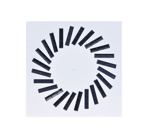
VWR-3A (RAL9016) • Square swirl diffuser with adjustable blades

Sold out
Original price £0.00 - Original price £0.00
Original price
£0.00
£0.00 - £0.00
Current price £0.00

Square swirl ceiling diffusers with adjustable blades

Article: A04400C400012

Brand

CAIROX

Application

For air supply in ventilation and air conditioning systems.

Material

Steel

Composition
  • Square swirl ceiling diffuser made of steel. The radial blades are individually adjustable and are developed for optimal diffusion, ensuring an instant mixture of primary and secondary air. Types 400/16, 500/16, and 600/16 have 16 blades, the 600/24 model has 24 blades
  • The first number (f.e. 400) represents the dimensions of the panel
Order Example

VWR-3A, 600, 24 + REV-B 600 + CRC 250

Explanation
VWR-3A = Diffuser type
600 = Plate size
24 = Slot quantity

Accessories
REV-B 600 = Plenum box for diffuser with 24 slots
CRC = Regulating valve for plenum box
250 = Plenum box connection diameter 250

Symbols and Specifications

Q = Air volume in m³/h
Ak = Effective surface (free area) in m²
B = Distance between the diffusers in m
H = Installation height of the diffusers in m
Vz = Maximum velocity at the occupied zone according to distance between the diffusers and installation height in m/s
Vk = Average effective velocity through the diffuser in m/s
X0.25 = Throw length in m at an end velocity Vt of 0,25m/s
Ps = Static pressure loss given in Pa
Lw(A) = Acoustic power in dB(A)


The throw X0.25 is given at an end velocity of 0.25m/s for a smooth ceiling without any obstacles.
The values are given for isothermal supply air. Throw distances for cooling conditions at -11K can be calculated by dividing the X0.25 values with factor 1.1. For heating purposes at Dt of +11K a multiplier of 1.1 should be applied to the given X0.25 value.
In order to achieve a high comfort level, selections can be made according to the maximal velocity at the occupied zone Vz. These values are given at distances between diffusers B and installation heights H. Velocities Vz lower than, or equal to 0,25m/s at the occupied zone are advised.
The pressure losses Ps are given for diffusers without damper of with fully opened damper.
The acoustic power values Lw(A) are given for diffusers without damper of with fully opened damper without room attenuation. Acoustic powers below 20dB(A) are mentioned as "<20" in the tables.
For all special requirements, please contact our engineering office.

Dimensions
VWR-3ASlotsAxA [mm]
400/1212395 x 395
400/1616395 x 395
500/1212495 x 495
500/1616495 x 495
600/1212595 x 595
600/1616595 x 595
600/2424595 x 595
Quick Selections
VWR-3A   1624
QAk0.015480.03718
B1.21.82.71.21.82.7
150 H=2.70.090.120.08   
VzH=3.20.060.070.05   
 H=3.80.040.050.04   
Vk2.7 
X0,251.1 
Ps4 
Lw(A)<20 
200 H=2.70.120.150.110.090.110.09
VzH=3.20.080.10.070.060.070.05
 H=3.80.050.070.050.040.050.04
Vk3.61.5
X0,251.50.9
Ps82
Lw(A)22<20
250 H=2.70.150.190.130.110.140.11
VzH=3.20.10.120.080.070.090.07
 H=3.80.070.080.060.050.060.05
Vk4.51.9
X0,251.81.2
Ps124
Lw(A)29<20
300 H=2.70.180.230.160.130.170.13
VzH=3.20.120.150.10.080.10.08
 H=3.80.080.10.070.060.070.06
Vk5.42.2
X0,252.21.4
Ps185
Lw(A)35<20
350 H=2.7   0.160.190.15
VzH=3.2   0.10.120.09
 H=3.8   0.070.080.07
Vk 2.6
X0,25 1.7
Ps 7
Lw(A) <20
400 H=2.7   0.180.220.17
VzH=3.2   0.110.140.11
 H=3.8   0.080.10.08
Vk 3
X0,25 1.9
Ps 9
Lw(A) 24
500 H=2.7   0.220.280.21
VzH=3.2   0.140.170.14
 H=3.8   0.10.120.09
Vk 3.7
X0,25 2.4
Ps 14
Lw(A) 30
600 H=2.7   0.270.330.26
VzH=3.2   0.170.210.16
 H=3.8   0.120.150.11
Vk 4.5
X0,25 2.8
Ps 20
Lw(A) 36